![]()
![]()
Microwave Techniques manufactures WR2300HH Waveguide Components with a wide range of high-power RF products and microwave solutions available.
The products listed below are simply a representation of our standard product line.
We also offer a wide array of custom solutions that are not represented in the list below.
If you do not see the WR2300HH waveguide component you require, contact sales@microwavetech.com to discuss your exact requirements with a technical sales engineer.
Please note all product data, specifications, and descriptions are subject to change at the sole discretion of Microwave Techniques and must be confirmed at the time of order.

| Items |
 66264-1 WR2300HH Waveguide Socket Flange |
 17376-1 WR2300HH Waveguide Thru Flange |
 82796-701 WR2300HH Waveguide E-Plane Sweep Bend |
 82797-701 WR2300HH Waveguide E-Plane Sweep Bend |
 73729-000 WR2300HH Waveguide H-Plane Miter Bend |
|||||
| Product # | 66264-1 | 17376-1 | 82796-701 | 82797-701 | 73729-000 | |||||
| Waveguide Size | WR2300HH | |||||||||
| Coaxial Size | ||||||||||
| Configuration | Sweep (H-Plane) | Sweep (E-Plane) | Miter Bend (H-Plane) | |||||||
| Configuration | Flange (Socket) | Flange (Thru) | ||||||||
| Frequency | 321-489 MHz | 321-489 MHz | 321-489 MHz | |||||||
| Bandwidth | ||||||||||
| Bandwidth | 168 MHz | 168 MHz | 5% Bandwidth | |||||||
| VSWR | 1.05:1 | 1.05:1 | 1.03:1 | |||||||
| Load VSWR | ||||||||||
| Sidearm VSWR | ||||||||||
| Transition VSWR | ||||||||||
| Pressure | 0.25 psig | 0.25 psig | 0.25 psig | |||||||
| Pressure | ||||||||||
| Pressure | ||||||||||
| Wall | 0.19 in | 0.19 in | ||||||||
| Wall | 0.19 in | 0.19 in | 0.19 in | |||||||
| Dimensional Drawing |
|
|
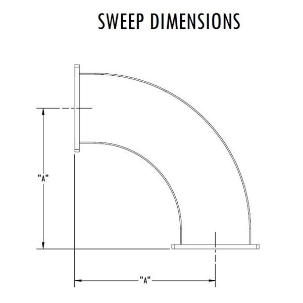 Waveguide Sweep Bends - Dimensions |
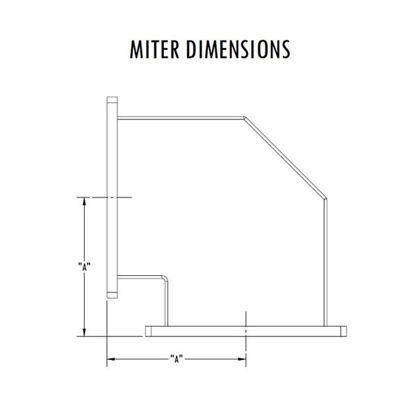 Waveguide Miter Bends - Dimensions |
|||||
| Length A | 51 in | 27 in | 18 in | |||||||
| Length | ||||||||||
| Length B | ||||||||||
| Power1 | 278 MW (Peak), 458 KW (Average) at 321 MHz 394 MW (Peak), 589 KW (Average) at 489 MHz | 278 MW (Peak), 458 KW (Average) at 321 MHz 394 MW (Peak), 589 KW (Average) at 489 MHz | 278 MW (Peak), 458 KW (Average) at 321 MHz 394 MW (Peak), 589 KW (Average) at 489 MHz | |||||||
| Power 12 | ||||||||||
| Power 2 | ||||||||||
| Power | ||||||||||
| Finish | ||||||||||
| Finish | None | None | RoHS Compliant Per MIL-DTL-5541 | RoHS Compliant Per MIL-DTL-5541 | RoHS Compliant Per MIL-DTL-5541 | |||||
| Material | Aluminum | |||||||||
| Flange Material | ||||||||||
| Interface | EIA-271 CPRF | |||||||||
| Interface - Coax | ||||||||||
| Interface - Waveguide | ||||||||||
| Coupler Interface | ||||||||||
| Waveguide Interface | ||||||||||
| Split | ||||||||||
| Isolation | ||||||||||
| Input | ||||||||||
| Directivity | ||||||||||
| Coupling &commat Center Frequency | ||||||||||
| Coupling Variation | ||||||||||
| Coupling | ||||||||||
| Amplitude Balance | ||||||||||
| Phase Balance | ||||||||||
| Minimum Isolation | ||||||||||
| Weight | 7.84 lb | 7.42 lb | 102.2 lb | 61.6 lb | 48.9 lb | |||||
| Paint | None | None | Microwave Techniques Grey | Microwave Techniques Grey | Microwave Techniques Grey | |||||
| Marking | None | None | Standard Label Containing PN, SN, QR Code | Standard Label Containing PN, SN, QR Code | Standard Label Containing PN, SN, QR Code | |||||
|
||||||||||