![]()
![]()

| Items |
 66541-1 WR975 (R9) Waveguide Socket Flange |
 10422-12 WR975 (R9) Waveguide Thru Flange |
 10426-702 WR975 (R9) Waveguide H-Plane Sweep Bend |
 10420-706 WR975 (R9) Waveguide E-Plane Sweep Bend |
 11110-000 WR975 (R9) Waveguide E-Plane Miter Bend |
|||||
| Product # | 66541-1 | 10422-12 | 10426-702 | 10420-706 | 11110-000 | |||||
| Waveguide Size | WR975 (R9) | |||||||||
| Coaxial Size | ||||||||||
| Configuration | Sweep (H-Plane) | Sweep (E-Plane) | Miter Bend (E-Plane) | |||||||
| Configuration | Flange (Socket) | Flange (Thru) | ||||||||
| Frequency | 757-1153 MHz | 757-1153 MHz | 757-1153 MHz | |||||||
| Frequency | 1153 MHz | 1153 MHz | 1153 MHz | |||||||
| Bandwidth | 396 MHz | 396 MHz | 5% Bandwidth | |||||||
| Bandwidth | ||||||||||
| VSWR | 1.05:1 | 1.05:1 | 1.03:1 | |||||||
| Load VSWR | ||||||||||
| Sidearm VSWR | ||||||||||
| Transition VSWR | ||||||||||
| Pressure | ||||||||||
| Pressure | 0.5 psig | 0.5 psig | 0.5 psig | |||||||
| Pressure | ||||||||||
| Waveguide Pressure | ||||||||||
| Max Coolant Pressure | ||||||||||
| Wall | 0.125 in | 0.125 in | ||||||||
| Wall | 0.125 in | 0.125 in | 0.125 in | |||||||
| Dimensional Drawing |
|
|
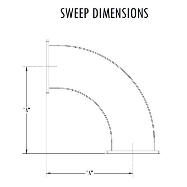 Waveguide Sweep Bends - Dimensions |
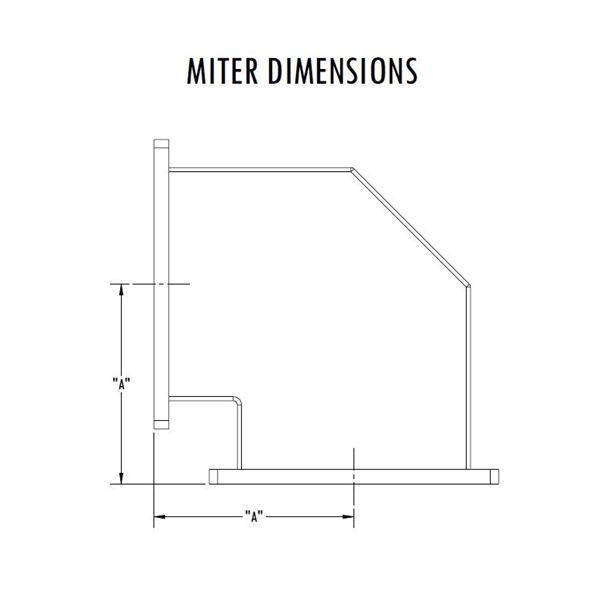 Waveguide Miter Bends - Dimensions |
|||||
| Length A | 21 in | 12 in | 9 in | |||||||
| Length | ||||||||||
| Length B | ||||||||||
| Power1 | 99.8 MW (Peak), 137 KW (Average) at 757 MHz 141 MW (Peak), 186 KW (Average) at 1153 MHz | 99.8 MW (Peak), 137 KW (Average) at 757 MHz 141 MW (Peak), 186 KW (Average) at 1153 MHz | 48.9 MW (Peak), 137 KW (Average) at 757 MHz 69.3 MW (Peak), 186 KW (Average) at 1153 MHz | |||||||
| Power 12 | ||||||||||
| Power 2 | ||||||||||
| Power | ||||||||||
| Max Power3 | ||||||||||
| Peak Power | ||||||||||
| Average Power | ||||||||||
| Port Power Monitors | ||||||||||
| Finish | None | None | RoHS Compliant Per MIL-DTL-5541 | RoHS Compliant Per MIL-DTL-5541 | RoHS Compliant Per MIL-DTL-5541 | |||||
| Finish | ||||||||||
| Material | Aluminum | |||||||||
| Flange Material | ||||||||||
| Interface | EIA-271 CPRF | |||||||||
| Interface | ||||||||||
| Interface - Coax | ||||||||||
| Interface - Waveguide | ||||||||||
| Coupler Interface | ||||||||||
| Cooing Interface | ||||||||||
| Waveguide Interface | ||||||||||
| Coolant Type | ||||||||||
| Inlet Temperature | ||||||||||
| Minimum Coolant Flow Rate | ||||||||||
| Isolation (dB) | ||||||||||
| Insertion Loss (dB) | ||||||||||
| Additional Marking | ||||||||||
| Tuning Capability | ||||||||||
| Operation | ||||||||||
| Cooling Media | ||||||||||
| Inlet Temp | ||||||||||
| Input Temp Tolerance | ||||||||||
| Minimum Flow Rate | ||||||||||
| Coolant Fittings | ||||||||||
| Split | ||||||||||
| Isolation | ||||||||||
| Input | ||||||||||
| Directivity | ||||||||||
| Coupling &commat Center Frequency | ||||||||||
| Coupling Variation | ||||||||||
| Coupling | ||||||||||
| Amplitude Balance | ||||||||||
| Phase Balance | ||||||||||
| Minimum Isolation | ||||||||||
| Direction | ||||||||||
| Mid-Band Gain (+/- 2 dB) | ||||||||||
| Weight | 2.93 lb | 3.54 lb | 18.0 lb | 12.9 lb | 11.9 lb | |||||
| Paint | None | None | Microwave Techniques Grey | Microwave Techniques Grey | Microwave Techniques Grey | |||||
| Marking | None | None | Standard Label Containing PN, SN, QR Code | Standard Label Containing PN, SN, QR Code | Standard Label Containing PN, SN, QR Code | |||||
|
||||||||||