![]()
![]()

| Items |
 65846-000 WR284 (R32) Waveguide Monitor Coupler |
 65846-701 WR284 (R32) Waveguide Monitor Coupler |
 67367-000 WR284 (R32) Waveguide Dual Directional Coupler |
 67367-701 WR284 (R32) Waveguide Dual Directional Coupler |
 67569-000 WR340 (R26) Waveguide Monitor Coupler |
|||||
| Type | Couplers | |||||||||
| Product # | 65846-000 | 65846-701 | 67367-000 | 67367-701 | 67569-000 | |||||
| Type | Waveguide Couplers | |||||||||
| Waveguide Size | WR284 (R32) | WR284 (R32) | WR284 (R32) | WR284 (R32) | WR340 (R26) | |||||
| Configuration | Waveguide Monitor Couplers | Waveguide Monitor Couplers | Waveguide Dual Directional Couplers | Waveguide Dual Directional Couplers | Waveguide Monitor Couplers | |||||
| Frequency | 2597-3958 MHz | 2450 MHz | 2597-3958 MHz | 2450 MHz | 2170-3306 MHz | |||||
| Bandwidth | 10% | 136.1 MHz | 10% | 136.1 MHz | 10% | |||||
| VSWR | 1.05:1 | |||||||||
| Sidearm VSWR | 1.25:1 | |||||||||
| Dimensional Drawing |
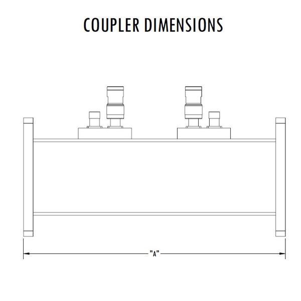 Waveguide Couplers - Dimensions |
|||||||||
| Length A | 6 in | 6 in | 9 in | 9 in | 6 in | |||||
| Power 11 | 4.19 MW (Peak), 6.29 KW (Average) at 2597 MHz | 3.70 MW (Peak), 5.29 KW (Average) at 2450 MHz | 4.19 MW (Peak), 6.29 KW (Average) at 2597 MHz | 3.70 MW (Peak), 5.29 KW (Average) at 2450 MHz | 6.36 MW (Peak), 9.92 KW (Average) at 2170 MHz | |||||
| Power 2 | 5.94 MW (Peak), 8.04 KW (Average) at 3958 MHz | 5.94 MW (Peak), 8.04 KW (Average) at 3958 MHz | 9.02 MW (Peak), 12.9 KW (Average) at 3306 MHz | |||||||
| Finish | RoHS Compliant Per MIL-DTL-5541 | |||||||||
| Material | Aluminum | |||||||||
| Pressure | 30 psig | 30 psig | 30 psig | 30 psig | 5 psig | |||||
| Waveguide Interface | EIA-271 CPRF | |||||||||
| Coupler Interface | Type N (Female) | |||||||||
| Directivity | 27 dB | |||||||||
| Coupling &commat Center Frequency | 40-75 (To Be Specified) dB | 50 dB | 40-75 (To Be Specified) dB | 60 dB | 40-75 (To Be Specified) dB | |||||
| Coupling Variation | +/- 1 dB | |||||||||
| Weight | 1.41 lb | 1.41 lb | 1.79 lb | 1.79 lb | 1.9 lb | |||||
| Paint | Microwave Techniques Grey | |||||||||
| Marking | Standard Label Containing PN, SN, QR Code | |||||||||
|
||||||||||