Flexible Waveguide
| Compare Items
Flexible Waveguide
By Waveguide Component Type
Microwave Techniques manufactures flexible waveguide with advanced designs and solutions for high-power RF and microwave applications. These flexible transmission lines are field proven to meet or exceed the highest standards in the industry.
Widely known for their high quality and excellent transmission capabilities, these versatile structures can absorb and allow for expansion and contraction in a microwave or RF feed.
Our process of brazing the seam off-center improves joint longevity and provides excellent electrical performance in high-power applications. This unique manufacturing process also eliminates the worry and potential for any splitting or leaking.
Often used for their mechanical advantages, flexible waveguides permit mechanical movement caused by thermal expansion. Another use case is for vibration isolation.
These units have the extraordinary ability to account for system flange misalignments.
An overview of our capabilities involving the manufacture of flexible waveguide includes:
Please note all product data, specifications, and descriptions are subject to change at the sole discretion of Microwave Techniques and must be confirmed at the time of order.
Flexible Waveguide
Microwave Techniques manufactures flexible waveguide with advanced designs and solutions for high-power RF and microwave applications. These flexible transmission lines are field proven to meet or exceed the highest standards in the industry.
Widely known for their high quality and excellent transmission capabilities, these versatile structures can absorb and allow for expansion and contraction in a microwave or RF feed.
Our process of brazing the seam off-center improves joint longevity and provides excellent electrical performance in high-power applications. This unique manufacturing process also eliminates the worry and potential for any splitting or leaking.
Often used for their mechanical advantages, flexible waveguides permit mechanical movement caused by thermal expansion. Another use case is for vibration isolation.
These units have the extraordinary ability to account for system flange misalignments.
An overview of our capabilities involving the manufacture of flexible waveguide includes:
- Custom lengths, assemblies, or configurations to meet your requirements
- A product line that includes straight sections, twists, offsets, and sweep bends
- Ideal electrical performance, special bend radii, optimum VSWR, maximum power handling
Please note all product data, specifications, and descriptions are subject to change at the sole discretion of Microwave Techniques and must be confirmed at the time of order.
Unit of Measure
Items |
![]() 77283-712 12" Semi Flexible WR284 (R32) Waveguide Straight Section |
![]() 77283-718 18" Semi Flexible WR284 (R32) Waveguide Straight Section |
![]() 77283-724 24" Semi Flexible WR284 (R32) Waveguide Straight Section |
![]() 79642-712 12" Semi Flexible WR340 (R26) Waveguide Straight Section |
![]() 79642-718 18" Semi Flexible WR340 (R26) Waveguide Straight Section |
|||||
Type | N/A Flexible Waveguide | |||||||||
Product # | N/A 77283-712 | N/A 77283-718 | N/A 77283-724 | N/A 79642-712 | N/A 79642-718 | |||||
Type | N/A Flexible Waveguide | |||||||||
Waveguide Size | N/A WR284 (R32) | N/A WR284 (R32) | N/A WR284 (R32) | N/A WR340 (R26) | N/A WR340 (R26) | |||||
Configuration | N/A Semi Flexible Waveguide - Straight Section | |||||||||
Frequency | N/A 2597-3958 MHz | N/A 2597-3958 MHz | N/A 2597-3958 MHz | N/A 2170-3306 MHz | N/A 2170-3306 MHz | |||||
Bandwidth | N/A 1361 MHz | N/A 1361 MHz | N/A 1361 MHz | N/A 1136 MHz | N/A 1136 MHz | |||||
VSWR | N/A 1.10:1 Full Band 1.05:1 at 10% Bandwidth | |||||||||
Pressure | N/A 30 psig | N/A 30 psig | N/A 30 psig | N/A 5 psig | N/A 5 psig | |||||
Wall | N/A 0.012 in | |||||||||
Dimensional Drawing |
N/A
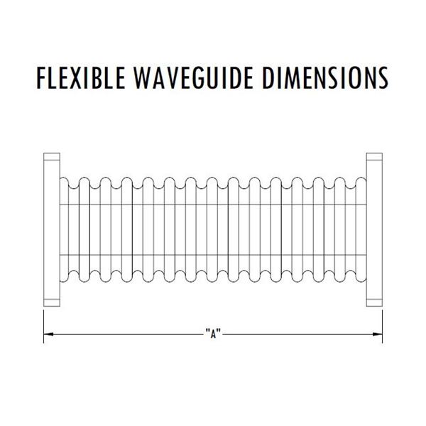
Flexible Waveguide - Dimensions |
|||||||||
Length A | N/A 12 in | N/A 18 in | N/A 24 in | N/A 12 in | N/A 18 in | |||||
Power1 | N/A 2.2 MW (Peak), 6.29 KW (Average) at 2597 MHz 3.12 MW (Peak), 8.04 KW (Average) at 3958 MHz | N/A 2.2 MW (Peak), 6.29 KW (Average) at 2597 MHz 3.12 MW (Peak), 8.04 KW (Average) at 3958 MHz | N/A 2.2 MW (Peak), 6.29 KW (Average) at 2597 MHz 3.12 MW (Peak), 8.04 KW (Average) at 3958 MHz | N/A 3.34 MW (Peak), 9.92 KW (Average) at 2170 MHz 4.74 MW (Peak), 12.9 KW (Average) at 3306 MHz | N/A 3.34 MW (Peak), 9.92 KW (Average) at 2170 MHz 4.74 MW (Peak), 12.9 KW (Average) at 3306 MHz | |||||
Material | N/A Aluminum Flange/ Phosphor Bronze Flex | |||||||||
Finish | N/A RoHS Compliant Per MIL-DTL-5541 Flange Face Bright Dip Flex | |||||||||
Interface | N/A EIA-271 CPRF | |||||||||
Weight | N/A 1.38 lb | N/A 1.78 lb | N/A 2.16 lb | N/A 2.27 lb | N/A 2.77 lb | |||||
Paint | N/A Microwave Techniques Black | |||||||||
Marking | N/A Stencil Containing PN, SN on Flange Edge | |||||||||
|