| Items |
 16104-9 WR284 (R32) Waveguide Gain Horn |
 16104-8 WR340 (R26) Waveguide Gain Horn |
 16104-7 WR430 (R22) Waveguide Gain Horn |
 16104-6 WR650 (R14) Waveguide Gain Horn |
 16104-5 WR770 (R12) Waveeuide Gain Horn |
|||||
| Type | Gain Horns | |||||||||
| Product # | 16104-9 | 16104-8 | 16104-7 | 16104-6 | 16104-5 | |||||
| Type | Waveguide Gain Horns | |||||||||
| Waveguide Size | WR284 (R32) | WR340 (R26) | WR430 (R22) | WR650 (R14) | WR770 (R12) | |||||
| Frequency | 2597-3958 MHz | 2170-3306 MHz | 1716-2614 MHz | 1135-1729 MHz | 958-1460 MHz | |||||
| Bandwidth | 1361 MHz | 1136 MHz | 898 MHz | 594 MHz | 502 MHz | |||||
| VSWR | 1.2:1 | |||||||||
| Mid-Band Gain (+/- 2 dB) | 18.2 dB | 15.4 dB | 15.1 dB | 17.2 dB | 15.4 dB | |||||
| Wall | 0.125 in | |||||||||
| Dimensional Drawing |
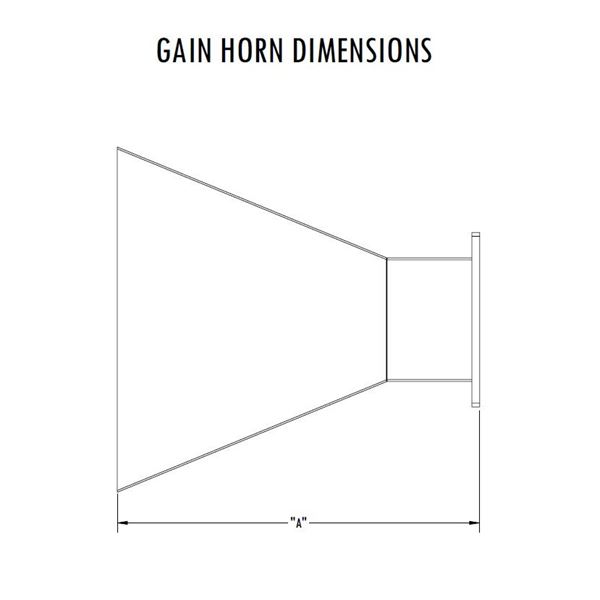 Waveguide Gain Horns - Dimensions |
|||||||||
| Length A | 18.5 in | 15.63 in | 23 in | 27 in | 23.3 in | |||||
| Power1 | 6.11 MW (Peak), 6.29 KW (Average) at 2597 MHz 8.67 MW (Peak), 8.04 KW (Average) at 3958 MHz | 9.29 MW (peak), 9.92 KW (Average) at 2170 MHz 13.2 MW (Peak), 12.9 KW (Average) at 3306 MHz | 14.9 MW (peak), 17.4 KW (Average) at 1716 MHz 21.1 MW (Peak), 22.8 KW (Average) at2614 MHz | 33.9 MW (Peak), 48.7 KW (Average) at 1135 MHz 48.1 MW (Peak), 64.9 KW (Average) at 1729 MHz | 47.6 MW (Peak), 74.4 KW (Average) at 958 MHz 67.5 MW (Peak), 101 KW (Average) at 1460 MHz | |||||
| Material | Aluminum | |||||||||
| Finish | RoHS Compliant Per MIL-DTL-5541 | |||||||||
| Interface | EIA-271 CPRF | |||||||||
| Weight | 5.6 lb | 4.6 lb | 8.1 lb | 15.4 lb | 15.4 lb | |||||
| Paint | Microwave Techniques Grey | |||||||||
| Marking | Standard Label Containing PN, SN, QR Code | |||||||||
| Pressure | ||||||||||
| Sidearm VSWR | ||||||||||
| Power 1 | ||||||||||
| Waveguide Interface | ||||||||||
| Coupler Interface | ||||||||||
| Directivity | ||||||||||
| Coupling &commat Center Frequency | ||||||||||
| Coupling Variation | ||||||||||
|
||||||||||