| Items |
 76039-000 WR284 (R32) Waveguide Hybrid |
 76039-711 WR284 (R32) Waveguide Hybrid |
 76039-702 WR284 (R32) Waveguide Hybrid |
 18946-000 WR340 (R26) Waveguide Hybrid |
 18946-701 WR340 (R26) Waveguide Hybrid |
|||||
| Type | Hybrids | |||||||||
| Product # | 76039-000 | 76039-711 | 76039-702 | 18946-000 | 18946-701 | |||||
| Type | Waveguide Hybrids | |||||||||
| Waveguide Size | WR284 (R32) | WR284 (R32) | WR284 (R32) | WR340 (R26) | WR340 (R26) | |||||
| Frequency | 2597-3958 MHz | 2700-2900 MHz | 2998 MHz | 2170-3306 MHz | 2450 MHz | |||||
| Bandwidth | 10% | 200 MHz | 136.1 MHz | 10% | 113.6 MHz | |||||
| VSWR | 1.10:1 | |||||||||
| Dimensional Drawing |
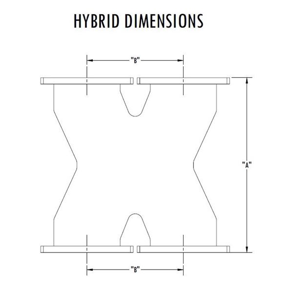 Waveguide Hybrids - Dimensions |
|||||||||
| Length A | 12 in | 12 in | 10 in | 12 in | 12 in | |||||
| Length B | 5 in | 5 in | 5 in | 5.75 in | 5.75 in | |||||
| Wall | 0.25 in | 0.25 in | 0.25 in | 0.125 in | 0.125 in | |||||
| Power 11 | 4.49 MW (Peak), 6.29 KW (Average) at 2597 MHz | 4.78 MW (Peak), 6.7 KW (Average) at 2700 MHz | 5.4 MW (Peak), 7.2 KW (Average) at 2998 MHz | 6.83 MW (Peak), 9.92 KW (Average) at 2170 MHz | 8.02 MW (Peak), 11.25 KW (Average) at 2450 MHz | |||||
| Power 2 | 6.37 MW (Peak), 8.04 KW (Average) at 3958 MHz | 5.22 MW (Peak), 7.15 KW (Average) at 2900 MHz | 9.67 MW (Peak), 12.9 KW (Average) at 3306 MHz | |||||||
| Finish | RoHS Compliant Per MIL-DTL-5541 | |||||||||
| Material | Aluminum | |||||||||
| Pressure | 30 psig | 30 psig | 30 psig | 5 psig | 5 psig | |||||
| Coupling | To Be Specified | 3 dB | 3 dB | To Be Specified | 3 dB | |||||
| Amplitude Balance | +/- 0.25 dB | |||||||||
| Phase Balance | 90 +/- 2 º | |||||||||
| Minimum Isolation | 28 dB | |||||||||
| Interface | EIA-271 CPRF | |||||||||
| Weight | 5.949 lb | 5.949 lb | 5.143 lb | 5.166 lb | 5.166 lb | |||||
| Paint | Microwave Techniques Grey | |||||||||
| Marking | Standard Label Containing PN, SN, QR Code | |||||||||
|
||||||||||