| Items |
 77686-701 WR284 (R32) Waveguide E-Plane Miter Bend |
 77685-701 WR284 (R32) Waveguide H-Plane Miter Bend |
 18839-703 WR340 (R26) Waveguide E-Plane Miter Bend |
 69522-000 WR340 (R26) Waveguide H-Plane Miter Bend |
 81974-708 WR430 (R22) Waveguide E-Plane Miter Bend |
|||||
| Type | Miter Bends | |||||||||
| Product # | 77686-701 | 77685-701 | 18839-703 | 69522-000 | 81974-708 | |||||
| Type | Waveguide Miter Bends | |||||||||
| Waveguide Size | WR284 (R32) | WR284 (R32) | WR340 (R26) | WR340 (R26) | WR430 (R22) | |||||
| Configuration | Miter Bend (E-Plane) | Miter Bend (H-Plane) | Miter Bend (E-Plane) | Miter Bend (H-Plane) | Miter Bend (E-Plane) | |||||
| Frequency | 2597-3958 MHz | 2597-3958 MHz | 2170-3306 MHz | 2170-3306 MHz | 1716-2614 MHz | |||||
| Bandwidth | 1361 MHz | 1361 MHz | 1136 MHz | 1136 MHz | 898 MHz | |||||
| VSWR | 1.05:1 | |||||||||
| Pressure | 30 psig | 30 psig | 5 psig | 5 psig | 3 psig | |||||
| Wall | 0.08 in | 0.08 in | 0.125 in | 0.125 in | 0.125 in | |||||
| Dimensional Drawing |
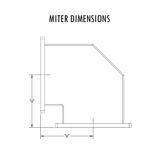 Waveguide Miter Bends - Dimensions |
|||||||||
| Length A | 4 in | 6 in | 4 in | 6 in | 4 in | |||||
| Power1 | 3.91 MW (Peak), 6.29 KW (Average) at 2597 MHz 5.55 MW (Peak), 8.04 KW (Average) at 3958 MHz | 7.98 MW (Peak), 6.29 KW (Average) at 2597 MHz 11.3 MW (Peak), 8.04 KW (Average) at 3958 MHz | 5.95 MW (peak), 9.92 KW (Average) at 2170 MHz 8.43 MW (Peak), 12.9 KW (Average) at 3306 MHz | 12.1 MW (Peak), 9.92 KW (Average) at 2170 MHz 17.2 MW (Peak), 12.9 KW (Average) at 3306 MHz | 9.51 MW (peak), 17.4 KW (Average) at 1716 MHz 13.5 MW (Peak), 22.8 KW (Average) at2614 MHz | |||||
| Material | Aluminum | |||||||||
| Finish | RoHS Compliant Per MIL-DTL-5541 | |||||||||
| Interface | EIA-271 CPRF | |||||||||
| Weight | 1.3 lb | 1.3 lb | 2.1 lb | 2.1 lb | 2.6 lb | |||||
| Paint | Microwave Techniques Grey | |||||||||
| Marking | Standard Label Containing PN, SN, QR Code | |||||||||
|
||||||||||