| Items |
 82865-702 WR284 (R32) Waveguide Test Termination Load - Fixed |
 76583-701 WR284 (R32) Waveguide Test Termination Load - Sliding |
 18960-702 WR340 (R26) Waveguide Test Termination Load - Fixed |
 78659-701 WR340 (R26) Waveguide Test Termination Load - Sliding |
 90134-701 WR430 (R22) Waveguide Test Termination Load - Fixed |
|||||
| Type | Termination Loads | |||||||||
| Product # | 82865-702 | 76583-701 | 18960-702 | 78659-701 | 90134-701 | |||||
| Type | Waveguide Test Termination Loads | |||||||||
| Waveguide Size | WR284 (R32) | WR284 (R32) | WR340 (R26) | WR340 (R26) | WR430 (R22) | |||||
| Configuration | Test Termination Load - Fixed | Test Termination Load - Sliding | Test Termination Load - Fixed | Test Termination Load - Sliding | Test Termination Load - Fixed | |||||
| Frequency | 2597-3958 MHz | 2597-3958 MHz | 2170-3306 MHz | 2170-3306 MHz | 1716-2614 MHz | |||||
| Bandwidth | 1361 MHz | 1361 MHz | 1136 MHz | 1136 MHz | 898 MHz | |||||
| VSWR | 1.05:1 | |||||||||
| Finish | RoHS Compliant Per MIL-DTL-5541 | |||||||||
| Material | Aluminum/ Low Power Microwave Absorber | |||||||||
| Dimensional Drawing |
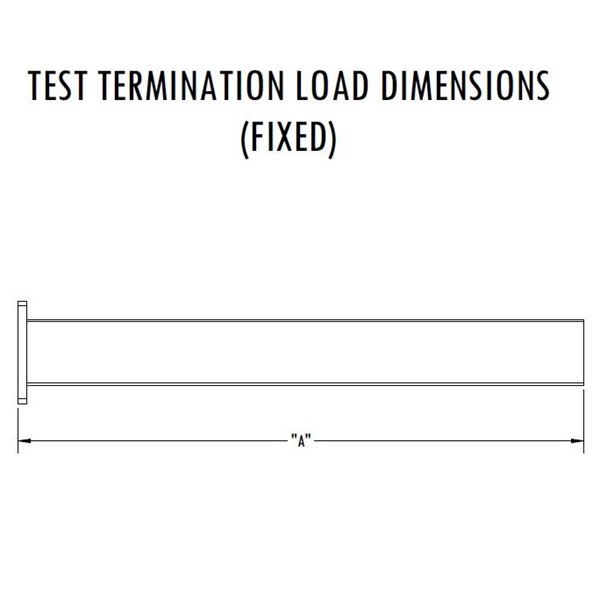 Waveguide Test Terminations - Fixed - Dimensions |
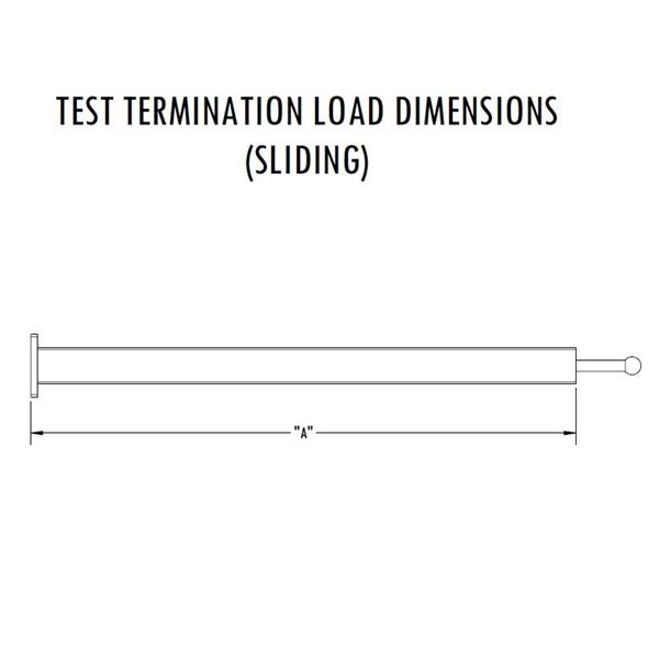 Waveguide Test Terminations - Sliding - Dimensions |
Waveguide Test Terminations - Fixed - Dimensions |
Waveguide Test Terminations - Sliding - Dimensions |
Waveguide Test Terminations - Fixed - Dimensions |
|||||
| Length A | 8.38 in | 25 in | 24 in | 36.13 in | 24.08 in | |||||
| Wall | 0.08 in | 0.08 in | 0.08 in | 0.08 in | 0.125 in | |||||
| Pressure | ||||||||||
| Power1 | VNA Power Only | |||||||||
| Impedance | ||||||||||
| Cooling Media | ||||||||||
| Inlet Temp | ||||||||||
| Input Temp Tolerance | ||||||||||
| Minimum Flow Rate | ||||||||||
| Max Coolant Pressure | ||||||||||
| Waveguide Pressure | ||||||||||
| Peak Power | ||||||||||
| Average Power | ||||||||||
| Coolant Fittings | ||||||||||
| Waveguide Pressure | ||||||||||
| Interface | EIA-271 CPRF | |||||||||
| Weight | 1.401 lb | 2.16 lb | 2.507 lb | 4.259 lb | 4.881 lb | |||||
| Paint | Microwave Techniques Grey | |||||||||
| Marking | Standard Label Containing PN, SN, QR Code | |||||||||
|
||||||||||